
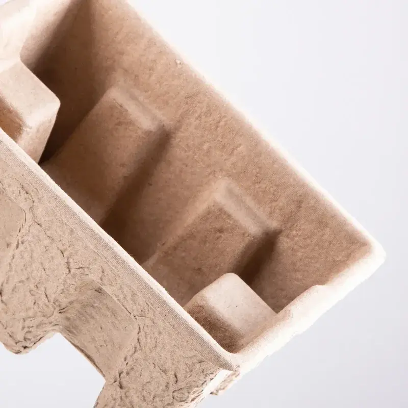
Custom Molded Pulp Inserts
Formed pulp cavities follow selected parts of the product profile. Its geometry must balance support, access and the available outer-pack space.
Standard MOQ: 500 pcs per style, size and artwork. Higher quantities may apply to special specifications. Sample timing and production timing are quoted for the project.
Specification for Molded Pulp Inserts
| Specification | Project input |
|---|---|
| Product dimensions and weight | Use the complete product, including protrusions and accessories, when defining support. |
| Contact points and cavities | Mark load-bearing points, delicate surfaces and areas that must remain clear. |
| Insert material | Identify the material or grade and review the required contact and handling conditions. |
| Removal access | Allow a practical way to insert and remove the contents without forcing sensitive parts. |
| Outer-box fit | Check the insert-to-box interface with the actual board, product and closing arrangement. |
| Quantity | Quantity per style, size and artwork design. Standard MOQ is 500 pieces; higher quantities may apply. |
| Artwork | PDF, AI or CDR artwork where available; JPG/PNG references and Excel specifications can support the brief. Files are reviewed for their intended use. |
| Delivery | Destination, target date and whether packaging should arrive assembled or flat, where applicable. |
Insert materials and contact surfaces
The quotation confirms the selected grade and compatible options.
| Material option | Specification and confirmation |
|---|---|
| Fibre construction | Request the proposed pulp material and relevant supporting information for the intended use. |
| Formed wall and cavity | Review cavity geometry and supporting surfaces with the product profile. |
| Surface appearance | Approve the visible fibre colour and texture on a formed sample; a rendered image is not a surface reference. |
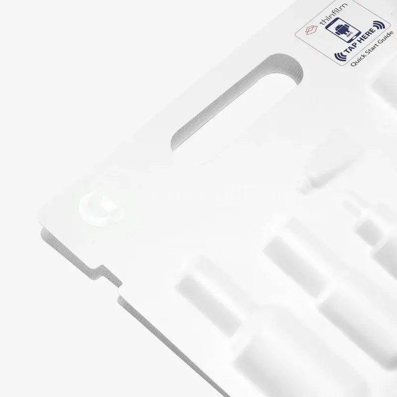
Product profile and outer-pack space
Product profiles, cavity depths and the available outer-pack space.
- Measurement reference: Give units and label product, internal or external dimensions. Include a drawing or reference sample if available.
- Multiple sizes: List quantities by size. A size change may require a revised structure, artwork or sample.
Visible pulp surfaces and markings
Use the visible fibre surface or a separate branded component as the design reference.
| Print preparation | Specification and confirmation |
|---|---|
| Print areas | Mark printed faces, unprinted areas, text and codes. The material and order requirements determine the printing method. |
| Colour reference | Provide CMYK artwork or a Pantone reference where available. Approve colour on the agreed material and sample; screen previews show layout. |
| Files and versions | Send PDF, AI or CDR artwork if available; JPG/PNG references and Excel specifications or data can support the brief. Files are reviewed before production. |
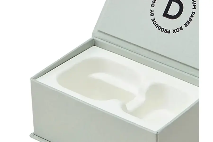
Visible surfaces and coverings
Availability depends on the material, structure and intended use.
- Contact surface: Identify delicate coatings, edges and areas that should not be rubbed or compressed. Review them with the proposed insert sample.
- Visible presentation: Describe the colour and appearance needed around the product. Printed paper faces or separate branded cards can be assessed where appropriate to the insert type.
- Edges and access points: Review cut or formed edges, finger access and the way the product is lifted out. A decorative surface must not obstruct removal or support.
Cavity layout and component fit
Cavity depth, wall shape and release from the forming tool affect the design. Provide the product geometry before committing to a final cavity layout.
Review formed cavities, nesting and finger access on the proposed moulded construction; confirm tooling from the approved geometry.
- Working layout: Send a drawing, reference or actual product. Identify fixed requirements and options to compare.
- Supply and assembly: Agree stacked, nested or fitted supply where the insert design allows it. Identify matching outer boxes and the assembly work expected at the packing site.
- Component matching: For a multi-part pack, list component sizes, assembly order and which parts the quotation includes.
Sample checks: cavity depth and tool release
Check a representative formed sample for fit, surface contact and removal. A digital model cannot confirm the actual texture or the fit of the formed material.
- Structural sample: Check dimensions, assembly, fit and opening or application with the actual contents where relevant.
- Printed sample: Check print areas, colour and finish. Record any differences between the sample process and bulk production.
- Production reference: Approve the sample and artwork version before production. Recheck affected parts after changes to dimensions, materials or functional components.
Sample fees, shipping and timing are quoted per project. A visual proof cannot replace physical checks.
Quotation, approval and production
Confirm the brief and quotation
Agree quantities by size and artwork, materials, printing, finishes, components, and any tooling or assembly charges.
Approve samples and files
Record the approved sample and artwork. Scheduling follows the required sample, artwork, deposit and order confirmations.
Produce and inspect
Agree inspection methods and acceptance criteria for materials, dimensions, print, appearance and relevant assembly or fit.
Pack and deliver
Production and transit times are assessed separately. Confirm the destination, transport arrangement and delivery responsibilities.
Related packaging options
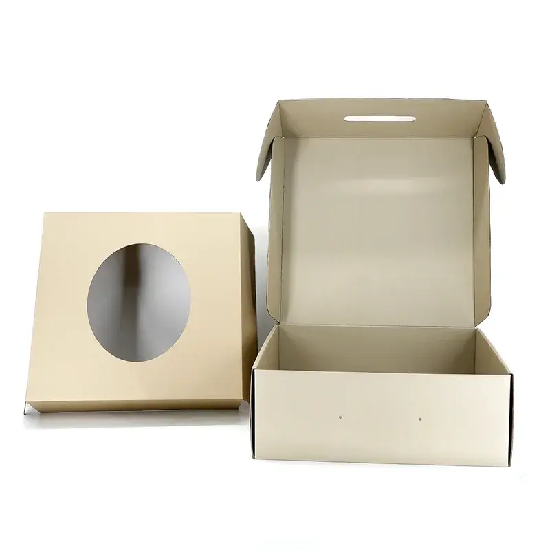
Custom Paperboard Inserts
Cut and folded paperboard supports products inside the outer pack. Tabs, platforms and openings can hold an item while preserving access.
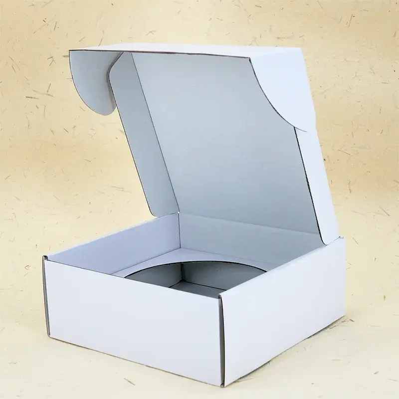
Custom Corrugated Inserts
Folded or die-cut corrugated components provide support and separation inside a carton. The insert layout is selected around the product and packing sequence.
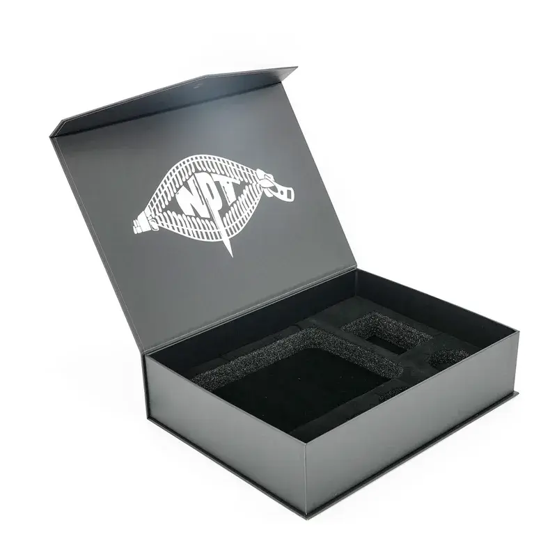
Custom EVA Foam Inserts
Cut or shaped EVA cavities organise products inside a box. Cavity dimensions and contact areas affect support and removal.
Compare Molded Pulp Inserts with related formats
| Option | When to consider it |
|---|---|
| Custom Molded Pulp Inserts | A shaped pulp tray can locate products through formed cavities and support surfaces. |
| Custom Paperboard Inserts | Folded paperboard can locate products through tabs, cut-outs and supporting panels. |
| Custom Corrugated Inserts | Corrugated components can support products with folded walls, pads or layered positions inside a shipping pack. |
Request pricing for molded pulp inserts
Send your product details, measurements, quantity per version and artwork direction to info@elevapack.com. Include the destination and any material, finish or assembly requirement you want us to review.
Custom Molded Pulp Inserts FAQ
Cavity depth, wall shape and release from the forming tool affect the design. Provide the product geometry before committing to a final cavity layout.
No. Check a representative formed sample for fit, surface contact and removal. A digital model cannot confirm the actual texture or the fit of the formed material.
Specify product profiles, cavity depths and the available outer-pack space. Use the visible fibre surface or a separate branded component as the design reference. Compatible materials and finishes are confirmed in the quotation.
The standard MOQ is 500 pcs per style, size and artwork. Special materials, constructions or multi-component sets may require more. Combined orders are assessed individually; the quotation confirms the applicable quantities.